A shaft coupling connects two rotating shafts so that power can pass from one to the other. Simple in concept — but the choice of coupling type, element material, and hub configuration has a direct impact on how long your machinery lasts, how much vibration it transmits, and how easy it is to maintain.
Get it right and the coupling is invisible: it connects the motor to the pump, gearbox, or conveyor and never needs a thought. Get it wrong and you're replacing bearings, chasing vibration faults, or dealing with a spider that keeps failing every few months.
This guide covers every coupling type AIMS stocks — jaw/spider, HRC, tyre, cone ring, rigid, and gear — with a focus on the selection decisions that actually matter: spider element material, pilot bore versus taper lock, misalignment type, and how to size for your torque. For a broader overview including disc, bellows and Oldham flexible coupling types, see the Flexible Coupling Guide.
What is a shaft coupling?
A shaft coupling transmits torque from a driver (electric motor, engine, gearbox output) to a driven machine (pump, fan, compressor, conveyor). It does this while accommodating the fact that the two shaft centrelines are never in perfect alignment — no matter how carefully the equipment is installed, thermal expansion, foundation movement, and manufacturing tolerances all introduce small deviations over time.
Beyond torque transmission and misalignment accommodation, couplings serve several other functions depending on the type:
- Vibration damping — absorbing torsional shock loads and reducing vibration transmission between driver and driven machine
- Electrical isolation — preventing stray currents travelling shaft-to-shaft (important in some pump and generator applications)
- Overload protection — the coupling element can be designed to fail before a more expensive component does
- Maintenance access — spacer-type designs allow pump cartridge removal without unbolting the motor
Flexible vs rigid: the first decision
The most fundamental choice is between a flexible coupling and a rigid coupling. This is not a preference — it is an engineering decision based on the alignment precision achievable at your installation:
- Flexible coupling: has an elastomeric, mechanical, or metallic flex element between the hubs. Accommodates angular, parallel, and axial misalignment within defined limits. Damps vibration. Required for most motor-to-pump, motor-to-gearbox, and motor-to-compressor connections.
- Rigid coupling: no flex element. Transmits torque without damping. The shafts must be in near-perfect alignment — any misalignment is transmitted directly into bearings and seals. Only appropriate where perfect alignment can be guaranteed and maintained, such as high-precision positioning systems or where two bearings already constrain a shared shaft.
The default for general industrial use is a flexible coupling. Rigid couplings are the exception, not the rule.
Coupling types at a glance
| Type | Flex element | Torque range | Misalignment tolerance | Typical use |
|---|---|---|---|---|
| Jaw / spider | Elastomeric spider (shear loaded) | Low–high (element dependent) | Moderate angular + parallel | Motor–pump, motor–gearbox, general drives |
| HRC | Elastomeric element (compression loaded) | Medium–high | Moderate angular + parallel | Motor–gearbox, heavy industrial drives |
| Flexible tyre | Rubber tyre ring | Medium | High angular + parallel | Applications with significant misalignment or shock |
| Cone ring | Polyurethane cone rings (pin and bush) | Medium–high | Moderate | Pumps, compressors, high shock loads |
| Rigid (split clamp) | None | High | None — requires perfect alignment | Precision shafts, shared-bearing systems |
| Gear | Crowned gear teeth | Very high | Angular + parallel (lubricated) | High-torque drives, steel plant, mining |
Jaw couplings
Jaw couplings — also called spider couplings or claw couplings — are the most widely used flexible coupling type in general industrial applications. They are simple, reliable, available in a wide range of sizes, and critically: the elastomeric spider can be replaced without moving the hubs or the machinery.
How a jaw coupling works
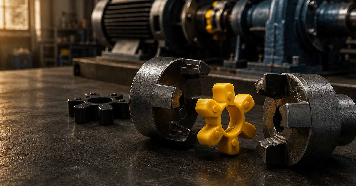
A jaw coupling consists of two metal hubs, each with protruding jaws or claws on the face, and a six-legged elastomeric element — the spider — that sits between them. Torque is transmitted through the jaws compressing the spider legs. The spider also accommodates small amounts of angular and parallel misalignment by deflecting under load.
The spider is loaded in shear, which means the legs are deformed sideways as they transmit torque. This is different from HRC couplings, where the element is loaded in compression.
Fail-safe operation
One of the key advantages of the jaw coupling design is fail-safe operation. If the spider element fails completely — split, worn, or disintegrated — the metal jaws of the two hubs eventually interlock and continue driving the load directly. The drive keeps running, albeit with noise and vibration, giving the operator time to detect the problem and schedule maintenance rather than suffering an unplanned shutdown.
Not all coupling types are fail-safe. In some designs, element failure means the drive drops out immediately. For critical applications, fail-safe behaviour is a selection criterion.
Standard jaw vs curved jaw
AIMS stocks both standard jaw couplings and curved jaw couplings. The difference is the jaw profile:
- Standard jaw: straight parallel jaws. Spider legs are compressed evenly along their full length. Standard for most applications.
- Curved jaw: the jaw faces are curved rather than straight. This distributes the load more gradually along the spider leg, reducing stress concentration at the jaw root. Suited to higher torque applications and where shock loads are frequent. The curved profile also gives slightly better angular misalignment tolerance.
Typical applications
Jaw couplings are the standard choice for connecting electric motors to pumps, fans, gearboxes, compressors, blowers, mixers, conveyors, and generator sets. They work in virtually any orientation and do not require lubrication (the spider element operates dry). Operating temperature range is set by the spider element material — typically −40°C to +100°C for NBR, higher for Hytrel.
The spider element: the real selection decision
When engineers talk about selecting a jaw coupling, the hub size is determined by bore and torque requirements. But the spider element material is the actual performance decision — it sets the torque capacity, vibration damping characteristics, misalignment tolerance, and operating temperature of the coupling.
Changing the spider material without changing the hub is entirely possible and common. The same hub in two different sizes of plant can perform very differently depending on which spider is fitted. This is where most incorrect coupling selections occur.
NBR — nitrile butadiene rubber
NBR spiders are typically black and have a hardness of approximately 80 Shore A. NBR is the standard, general-purpose spider material and the right default for most applications.
- Strengths: excellent vibration damping, highest misalignment tolerance of the four materials, lowest heat generation under cyclic loading, good oil and fuel resistance, cost-effective
- Limitations: lowest torque capacity of the four materials, maximum temperature typically 80–100°C continuous
- Use when: vibration damping is important, some misalignment exists, operating temperatures are moderate, general motor-to-pump or motor-to-gearbox applications
Polyurethane
Polyurethane (PU) spiders are typically yellow or orange and have a hardness of approximately 95 Shore A — significantly harder than NBR. They carry approximately two to three times the torque of an NBR spider of the same hub size.
- Strengths: substantially higher torque capacity than NBR, better wear resistance, good oil resistance, moderate temperature range
- Limitations: reduced vibration damping (harder material damps less), reduced misalignment tolerance, generates more heat under cyclic loading (hysteresis), higher cost than NBR
- Use when: torque requirements exceed what NBR can handle, alignment is good, vibration damping is less critical, applications with high peak torques or frequent starting
Hytrel
Hytrel is a thermoplastic polyester elastomer — tan or white in colour, very stiff, with a hardness of approximately 55 Shore D (a harder scale than Shore A). It behaves almost like a semi-rigid element.
- Strengths: highest torque capacity of the three elastomeric options, excellent high-temperature resistance (continuous to 120°C, short-term higher), good chemical resistance, can be used in washdown environments
- Limitations: minimal vibration damping, very low misalignment tolerance (angular misalignment ratings typically halved compared to NBR), generates significant heat if misalignment is present, not suitable as a general-purpose replacement for NBR
- Use when: high torque in a small coupling envelope is required, operating temperatures exceed NBR/PU capability, alignment is excellent and maintained
Snap wrap element
The snap wrap (also called split spider) element is not a different elastomer — it is available in NBR or PU — but the geometry is different. Rather than six separate legs, the snap wrap is a single annular element that wraps around the hubs and can be snapped into place radially without axial access.
The practical advantage: you can replace the spider without sliding either hub along its shaft. Where machinery is closely coupled, or where axial movement is restricted by a thrust bearing or mechanical seal, the snap wrap allows element replacement in situ. This can reduce a planned maintenance stop from hours to minutes.
Spider element comparison summary
| Property | NBR | Polyurethane | Hytrel |
|---|---|---|---|
| Colour (typical) | Black | Yellow / orange | Tan / white |
| Hardness | ~80 Shore A | ~95 Shore A | ~55 Shore D |
| Torque capacity (relative) | 1× | 2–3× | 3–4× |
| Vibration damping | Excellent | Moderate | Low |
| Misalignment tolerance | Highest | Moderate | Lowest |
| Max continuous temp | ~100°C | ~80°C | ~120°C |
| Oil resistance | Good | Good | Excellent |
| Best for | General purpose, vibration critical | Higher torque, good alignment | High torque + high temp, excellent alignment |
The spider as a fuse
Design the spider to be the weakest element in the drive — intentionally. If an overload occurs, the spider fails first, protecting the motor shaft, pump impeller, gearbox, and keyways from the energy of the event. Replacing a spider element is inexpensive. Replacing a sheared shaft or a damaged mechanical seal is not.
This principle means you should resist the temptation to always fit the hardest spider available. A Hytrel spider that transmits the full shock load into the machine defeats the purpose of a flexible coupling entirely.
When to replace the spider
Inspect the spider during planned maintenance stops. Replace when:
- Any leg shows cracking, chunking, or deformation
- Leg cross-section has worn to approximately 75% of original thickness
- Rubber debris is visible around the coupling
- Coupling is producing a clunking or knocking on load change (backlash due to worn legs)
HRC couplings
HRC couplings (the letters stand for the original manufacturer's product code, now used generically) look similar to jaw couplings but operate on a fundamentally different principle. Understanding the difference is important because the two types are often confused.
How HRC differs from jaw coupling
In a jaw coupling, the spider legs sit between the jaw faces and are loaded in shear — twisted sideways as torque is applied. In an HRC coupling, the elastomeric element sits between two flanged hubs and is loaded in compression — squeezed between the hub pins and the bore of the element as torque is transmitted.
Compression loading provides higher torque capacity for the same outside diameter compared to shear loading. The HRC element can also be replaced while the hubs remain on the shaft, similar to the snap wrap jaw element.
HRC element materials
AIMS stocks HRC elements in both nitrile rubber (NBR) and polyurethane:
- NBR element: standard duty, good vibration damping, moderate torque
- Polyurethane element: higher torque capacity, better wear resistance, reduced damping
HRC coupling hub types: Type F and Type H
HRC hubs are available in two taper lock configurations depending on access direction:
- Type F (flange end): the taper lock bush is inserted from the flange face of the hub — the side facing the element. This is the more common configuration.
- Type H (hub end): the taper lock bush is inserted from the outer face of the hub — away from the element. Used where access to the flange face is restricted after installation.
Both types are also available in pilot bore, for direct machining to shaft size.
Typical HRC applications
HRC couplings are widely used in heavy industrial drives — motor to gearbox connections, conveyor head drives, compressor drives, and crusher drives. The compression-loaded element handles high torque reliably and the modular design suits applications where the coupling is dismantled frequently for maintenance.
Rigid couplings
Rigid couplings transmit torque without any flex element. The two hubs are clamped directly together, making a solid mechanical connection. There is no vibration damping and no misalignment accommodation.
Split clamp (sleeve) type
AIMS stocks split clamp rigid couplings — a two-piece clamshell design that bolts around both shaft ends. They are available with a black oxide finish for corrosion resistance.
The split clamp design offers an advantage over solid sleeve rigid couplings: the coupling can be installed and removed radially without sliding it along the shaft. This simplifies installation in restricted spaces.
When to use a rigid coupling
Rigid couplings are appropriate when:
- The two shafts are already constrained by bearings that prevent relative movement — for example, a line shaft supported at multiple points where each section is separately aligned
- The application requires zero torsional compliance — certain precision positioning and testing systems
- The shaft ends must be locked together rigidly to form a continuous shaft of a specific stiffness
When NOT to use a rigid coupling
Do not use a rigid coupling to connect a motor shaft directly to a pump or gearbox shaft unless perfect, permanently maintained alignment is certain. Any angular or parallel misalignment with a rigid coupling is transmitted directly into the shaft bearings and seals as a rotating bending moment. This accelerates bearing wear, causes seal leakage, and leads to shaft fatigue failure. The coupling itself will not fail — the machinery around it will.
Flexible tyre couplings
Flexible tyre couplings use a toroidal rubber tyre element — shaped like a donut cross-section — bolted between two flanged hubs. The tyre element deforms under torque and misalignment, providing high flexibility and excellent shock absorption.
Characteristics
- Misalignment tolerance: higher than jaw or HRC couplings. The tyre can accommodate larger angular and parallel offsets, making tyre couplings suitable for applications where precision alignment is difficult to achieve or maintain — construction equipment, quarry plant, portable generators.
- Shock absorption: the large rubber volume of the tyre element provides excellent torsional damping. Well-suited to diesel engine drives with high torque variation.
- Maintenance: the tyre element is typically split (two-piece) for in-situ replacement without moving hubs.
- Speed rating: the large diameter of the tyre element limits maximum operating speed. Not suitable for high-speed drives.
FRAS tyre couplings
AIMS stocks flexible tyre couplings in FRAS (Fire Resistant and Anti-Static) specification. FRAS materials are a mandatory requirement for power transmission components used in underground mining and other hazardous area applications where flammable atmosphere or accumulated coal dust is a risk. FRAS tyre couplings carry the required certification for compliance with Australian mining regulations.
Cone ring couplings
Cone ring couplings are less well-known than jaw or HRC designs but offer a distinct combination of high torque capacity and good vibration damping. They are worth understanding as a specific solution for demanding applications.
How cone ring couplings work
A cone ring coupling consists of a pin half (with drive pins) and a bush half (with tapered bores). Polyurethane cone rings — shaped as truncated cones — sit over each pin and engage with the corresponding tapered bore in the bush half. Torque is transmitted through the conical contact surface, which places the polyurethane element under a combination of compression and shear.
The cone geometry is self-centring — the elements locate precisely under load, minimising backlash. This makes cone ring couplings a strong choice for applications with reversing loads or frequent start-stop cycles where backlash in a jaw coupling would cause shock.
Pilot bore and taper lock variants
AIMS stocks cone ring couplings in both configurations:
- Pilot bore: hubs are supplied with a standard small pilot bore and must be machined to the required shaft diameter and keyway. Suitable for custom shaft sizes and workshop machining.
- Taper lock: hubs accept standard taper lock bushes for rapid, precise shaft mounting without specialist machining.
When to choose a cone ring over a jaw coupling
Cone ring couplings are suited to applications where:
- Torque requirements are at the upper limit of what a jaw coupling of the same outside diameter can handle
- Reversing loads or back-driving create backlash problems with a standard jaw coupling
- Good vibration damping is needed alongside higher torque capacity
- Frequent element inspection and replacement is required (elements are accessible from the OD)
Gear couplings
Gear couplings transmit torque through meshing crowned gear teeth — an external gear on each hub engages with an internal gear in a sleeve. The crowned tooth profile allows angular and parallel misalignment while transmitting very high torque in a compact envelope.
Unlike elastomeric coupling types, gear couplings require periodic lubrication — grease-packed sleeves are standard. They are suited to high-torque, high-speed applications in steel mills, mining drives, paper mills, and heavy machinery where the torque density of an elastomeric coupling would require an impractically large coupling diameter.
AIMS stocks gear couplings in a range of sizes. For specific size and torque specifications, contact the team directly.
Pilot bore vs taper lock
This is one of the most common points of confusion when ordering coupling hubs. Pilot bore and taper lock describe the bore configuration of the hub — how the hub attaches to the shaft — not different coupling types.
Pilot bore
A pilot bore hub is supplied with a small standard bore (the "pilot" bore) and must be machined to the required shaft diameter, keyway width, and keyway depth before installation. The hub is secured to the shaft with a key and typically one or two setscrews over the key.
When to use pilot bore:
- Non-standard shaft diameters that do not correspond to standard taper lock bush sizes
- Workshop has a lathe and machining capability on site
- Cost-sensitive applications — pilot bore hubs are less expensive than pre-bored or taper lock equivalents
- One-off or prototype applications
Taper lock
A taper lock hub accepts a standard taper lock bush — a split tapered sleeve that locks onto the shaft using the wedging action of the taper as the bush screws are tightened. The bush and hub assembly is self-centring, provides a high-friction grip on the shaft, and can be released and refitted without damage to the shaft surface.
When to use taper lock:
- Standardised shaft sizes (standard taper lock bush range covers most common shaft diameters)
- Applications requiring frequent removal and refitting — the taper lock releases cleanly without shaft damage
- Higher torque applications where a keyway setscrew alone is marginal
- Sites with standardised on taper lock bush inventory across multiple drive types
Why hubs slide off shafts
Hub migration — the hub gradually slides back along the shaft during operation — is a recurring maintenance problem with pilot bore hubs. The causes in order of frequency:
- Setscrew undertorqued — the most common cause. Use a torque wrench, not a feel check.
- Setscrew positioned over a smooth bore section, not over the key — the key carries axial load; the setscrew alone cannot.
- No key fitted — some pilot bore hubs are installed on smooth shafts with setscrew only. This is inadequate for anything other than very light torque at low speed.
- Shaft surface too smooth — a light knurl or shaft shoulder improves retention significantly for critical applications.
If a pilot bore hub keeps migrating despite correct setscrew torque, the correct solution is a taper lock bush conversion or a shaft shoulder, not a heavier setscrew.
Shaft misalignment: types and tolerances
Understanding misalignment type matters for coupling selection. Flexible couplings are rated for specific maximum misalignment values — and exceeding them even with a flexible coupling causes bearing damage, seal leakage, and premature coupling element failure.
The critical point that is commonly misunderstood: a flexible coupling can tolerate more misalignment than the connected machinery can. Just because the coupling is not failing does not mean the misalignment is acceptable. The bearings and seals of the pump or gearbox may be taking loads that the coupling is successfully absorbing — but that absorption is reflected as added bearing load, not eliminated.
| Misalignment type | Description | Typical max (jaw coupling) | Which couplings handle best |
|---|---|---|---|
| Angular | Shaft centrelines intersect at an angle — one shaft is tilted relative to the other | 1.0° (NBR spider) | Jaw (NBR), tyre, cone ring |
| Parallel (radial offset) | Shaft centrelines are parallel but offset — one shaft is laterally displaced from the other | 0.3–0.5 mm | Jaw (NBR), tyre, HRC |
| Axial (end float) | Shaft moves axially — towards or away from the other shaft | 1–2 mm | Jaw, HRC, tyre, cone ring |
| Combined | Angular + parallel simultaneously — the real-world condition | Reduced from single-type values | Tyre coupling (highest combined tolerance) |
These figures are guides. Always verify against the manufacturer's published misalignment table for the specific coupling size and element type selected. Harder spider materials (PU, Hytrel) have significantly reduced misalignment tolerances compared to NBR.
Coupling selection guide
| Application | Load type | Alignment quality | Recommended coupling | Element / notes |
|---|---|---|---|---|
| Electric motor → centrifugal pump | Uniform, low shock | Good | Jaw coupling | NBR spider, standard bore or taper lock |
| Electric motor → centrifugal pump, high torque | Uniform, moderate | Good | Jaw coupling | PU spider or HRC coupling |
| Electric motor → positive displacement pump | High starting torque, cyclic | Good | Jaw (curved jaw) or HRC | PU spider; size for starting torque not running torque |
| Electric motor → gearbox | Moderate shock | Moderate–good | Jaw or HRC coupling | PU spider or NBR depending on shock frequency |
| Motor → conveyor or mixer (high shock) | High shock loads | Moderate | Jaw (NBR) or tyre coupling | NBR for damping; tyre if severe shock or misalignment |
| Diesel engine → generator or pump | High torsional variation | Variable | Tyre coupling or jaw (NBR) | Tyre preferred for high torsional variation and misalignment |
| Motor → compressor (reciprocating) | Cyclic, high peak torque | Good required | HRC or cone ring | Jaw spider couplings not suitable for reciprocating compressors |
| Reversing drive (crane, hoist) | Reversing load | Good | Cone ring coupling | Self-centring under reversal; low backlash |
| High-torque drive (crusher, mill) | Very high torque, shock | Variable | Gear coupling or HRC (large) | Gear coupling for highest torque density |
| Underground mining | Any | Any | FRAS tyre coupling | FRAS certification required; check applicable standard |
| Precision positioning or line shaft | Low, uniform | Perfect — maintained | Rigid coupling (split clamp) | Only where shafts are fully constrained by bearings |
Sizing a coupling
Coupling sizing starts with torque, not with shaft diameter. Shaft diameter determines the minimum bore size needed; torque determines the coupling size and element type.
Step 1: Determine rated torque
Rated torque (T) can be calculated from motor power and speed:
T (N·m) = (Power in kW × 9550) ÷ Speed in RPM
For example: a 15 kW motor running at 1,450 RPM produces a rated torque of (15 × 9550) ÷ 1450 = 98.8 N·m.
Step 2: Apply service factor
The service factor (SF) accounts for real-world conditions — shock loads, frequent starting, variable torque, type of driven machine — that cause instantaneous torques higher than the steady-state rated torque. Design torque = rated torque × service factor.
| Application type | Typical service factor |
|---|---|
| Centrifugal pumps, fans, blowers (uniform load) | 1.0–1.25 |
| Centrifugal compressors, conveyors (light shock) | 1.25–1.5 |
| Positive displacement pumps, mixers (moderate shock) | 1.5–2.0 |
| Reciprocating compressors, crushers (heavy shock) | 2.0–3.0 |
| Reversing drives, cranes, hoists | 2.0–3.5 |
Using the example above: if driving a centrifugal pump, SF = 1.25. Design torque = 98.8 × 1.25 = 123.5 N·m. Select a coupling with a rated torque (for the chosen spider material) that exceeds 123.5 N·m.
Step 3: Check bore capacity
Confirm the coupling hub's maximum bore accommodates both shaft diameters. If the motor shaft and pump shaft are different sizes, the two hubs can have different bore sizes — this is standard and does not require any modification to the spider element.
Do not oversize
It is tempting to fit the next size up "for safety." Resist this for elastomeric couplings. The coupling element is designed to be the sacrificial component in an overload event. Oversizing eliminates that protection and transfers the overload energy into shafts, keyways, and machinery. Match the design torque; do not over-engineer it.
Installation essentials
Hub installation
- Clean the shaft and hub bore thoroughly. Remove any burrs or raised material from keyways.
- Check the shaft fits the hub bore cleanly by hand or with light mallet taps. Forcing a hub onto an oversized bore damages both.
- Fit the key before pressing the hub on. Ensure the key is seated fully in the shaft keyway and does not stand proud of the shaft OD.
- Position the hub at the correct axial location — typically flush with the shaft end or at the specified hub gap position per the manufacturer's drawing.
- Tighten setscrews to the manufacturer's torque specification. A torque wrench is not optional for this step.
Hub gap
The gap between the two hub faces must be set correctly before the spider is installed. Too small a gap overloads the spider axially; too large a gap allows the spider to shift under load. The correct gap dimension is specified in the coupling catalogue for each size — typically 2–5 mm depending on coupling size.
Alignment
Align the shafts before fitting the spider. Use dial indicators or laser alignment equipment for machinery above 15 kW or above 1,500 RPM. Below these thresholds a straight edge and feeler gauges may suffice for NBR spider applications.
Flexible couplings accommodate residual misalignment after alignment — they do not substitute for alignment. Align first, then connect.
Spider installation
Standard spiders are inserted axially — one hub is slid along the shaft or the spider is fed in from the side. Snap wrap elements are installed radially with no axial movement required. Ensure spider legs are fully engaged in the jaw pockets before running.
Guard
All rotating couplings must be guarded in accordance with AS 4024.1 (Safety of Machinery — Guards). Confirm the guard design allows access for spider inspection without complete removal.
Connect it right. Run it longer.
Shop jaw, HRC, tyre & cone ring couplings — plus spider elements
From pilot bore jaw couplings to taper lock HRC and tyre couplings — AIMS Industrial stocks shaft couplings and replacement spider elements in NBR, PU, and Hytrel for motors, pumps, gearboxes and conveyors, ready to ship Australia-wide.
Frequently asked questions
What is a shaft coupling and why is it needed?
A shaft coupling connects two rotating shafts to transmit power from a driver (motor, engine) to a driven machine (pump, fan, gearbox). It also accommodates the small angular and parallel misalignment that is always present between any two separately mounted shaft centrelines, absorbs shock loads, and protects against overload. Without a coupling, any misalignment between shafts creates a rotating bending moment that damages bearings and seals in both machines.
What's the difference between a flexible and a rigid coupling?
A flexible coupling has an elastomeric or mechanical element between the hubs that accommodates misalignment and damps vibration. A rigid coupling has no flex element — the hubs connect directly, making a solid shaft. Rigid couplings transmit misalignment forces straight into machine bearings. They are only suitable where shafts are already constrained by bearings that prevent relative movement, such as line shafts or precision positioning systems. For motor-to-pump and motor-to-gearbox connections, always use a flexible coupling.
What is a jaw coupling spider and what does it actually do?
The spider is the six-legged elastomeric element between the two metal hubs in a jaw coupling. It transmits torque by being compressed between the jaw faces as the drive rotates, accommodates shaft misalignment by deflecting slightly under load, and damps torsional shock and vibration. If an overload occurs, the spider is designed to fail before more expensive components do — it acts as a sacrificial fuse for the drivetrain. Jaw couplings are also fail-safe: if the spider fails completely, the metal jaws eventually interlock and continue driving (noisily) until the machine can be shut down for maintenance.
NBR, polyurethane or Hytrel — which spider element should I use?
NBR (black, ~80 Shore A) is the general-purpose default: best vibration damping, highest misalignment tolerance, suited to most motor-pump and motor-gearbox applications. Polyurethane (yellow/orange, ~95 Shore A) carries two to three times the torque of NBR in the same hub size but damps less and tolerates less misalignment — use it when NBR cannot handle the torque and alignment is good. Hytrel (tan/white, ~55 Shore D) offers the highest torque capacity and handles up to 120°C continuously, but provides almost no damping and requires excellent, maintained alignment — it behaves more like a semi-rigid element. When in doubt, start with NBR.
What is an HRC coupling and how is it different from a jaw coupling?
In a jaw coupling, the elastomeric spider is loaded in shear — the jaws squeeze the spider legs sideways as torque is transmitted. In an HRC coupling, the rubber element sits between flanged hubs and is loaded in compression as the drive pins push through the element. Compression loading gives higher torque capacity for the same outside diameter. HRC couplings are available with nitrile or polyurethane elements and with pilot bore or taper lock hubs (Type F or Type H configuration). They are common in heavy industrial motor-to-gearbox applications where jaw coupling sizes would be impractically large.
Can I use a flexible coupling to fix a misaligned shaft?
No — and this is the most common coupling misconception. A flexible coupling accommodates residual misalignment after correct alignment has been achieved. It does not substitute for alignment. A flexible coupling may tolerate 0.3–0.5 mm of parallel offset without failing; the pump or gearbox bearing it is connected to may only be able to accept 0.05 mm before fatigue loads accelerate wear. The coupling survives; the machine bearings do not. Align first with dial indicators or laser equipment, then connect the coupling.
What are the three types of shaft misalignment and which coupling handles each?
Angular misalignment is where the two shaft centrelines meet at an angle — one shaft is tilted relative to the other. Parallel (radial) misalignment is where the centrelines are parallel but offset laterally. Axial misalignment is where one shaft moves towards or away from the other along its centreline. Real installations usually have a combination of all three. Tyre couplings handle the largest combined misalignment; jaw couplings with NBR spiders handle moderate combined misalignment; HRC and cone ring couplings are similar to jaw; Hytrel spiders and gear couplings require near-perfect alignment.
What is the difference between a pilot bore and a taper lock hub?
Both are hub configurations — how the hub attaches to the shaft — not different coupling types. A pilot bore hub is supplied with a small standard bore that must be machined to the required shaft diameter and keyway in a lathe before installation. It is secured with a key and setscrew. A taper lock hub accepts a standard taper lock bush — a split tapered sleeve that locks onto the shaft when the bush screws are tightened. Taper lock hubs are self-centring, provide excellent shaft grip, and can be released cleanly without damaging the shaft. Use pilot bore when shaft sizes are non-standard or machining is available; use taper lock where standard shaft sizes are used and frequent removal is expected.
How do I size a coupling for my application?
Calculate rated torque from motor power and speed: T (N·m) = (kW × 9550) ÷ RPM. Apply a service factor for the application type — 1.0–1.25 for centrifugal pumps and fans, 1.5–2.0 for positive displacement pumps and mixers, 2.0–3.0 for reciprocating compressors and crushers. Design torque = rated torque × service factor. Select a coupling whose rated torque for the chosen element material exceeds the design torque. Then confirm the hub bores accommodate both shaft diameters. Do not oversize — the coupling element is meant to be the sacrificial weak point in an overload.
Why does my coupling spider keep failing prematurely?
The five most common causes: (1) Excessive misalignment — the coupling is being asked to accommodate more offset than its design allows; re-align the drive. (2) Wrong element material — if the torque exceeds NBR capacity, upgrade to PU; if operating temperature exceeds element rating, change material. (3) Undertorqued hubs — hub migration under load causes the jaws to run out of position, unevenly loading the spider legs. (4) Chemical attack — oil, coolant, or solvent contact on NBR spiders causes swelling and loss of mechanical properties. (5) Overloading — if the spider is failing in shear, the driven machine may be stalling or jamming. The spider failing is the symptom; the root cause is elsewhere in the system.
Why does my coupling hub keep sliding off the motor or pump shaft?
Hub migration is almost always one of four causes: the setscrew was not torqued correctly (by far the most common — use a torque wrench); the setscrew is positioned over the smooth bore section rather than directly over the key (the key carries the axial load; the setscrew over a smooth bore cannot hold axially); no key is fitted (setscrew-only retention is only adequate for light, low-speed drives); or the shaft has no shoulder or undercut for the hub to locate against. If the hub migrates despite correct torque, the solution is a taper lock bush conversion or the addition of a shaft shoulder.
How do I replace a jaw coupling spider without moving the machinery?
With a standard spider, the hubs must be slid apart axially far enough to remove and refit the spider legs — this may require disconnecting the shaft from one machine. A snap wrap (split) spider solves this: the element wraps around the jaws and is snapped in radially from the outside, with no axial hub movement required. Where machinery is closely coupled, where axial movement is restricted by a mechanical seal or thrust bearing, or where rapid element replacement is needed to minimise downtime, specifying a snap wrap spider at installation eliminates the problem. The snap wrap is available in NBR and polyurethane.
What is a cone ring coupling and when should I use one instead of a jaw coupling?
A cone ring coupling uses polyurethane cone rings engaged on drive pins between a pin half and a bush half, loaded in a combination of compression and shear. The conical geometry is self-centring, which minimises backlash under reversing loads — an advantage jaw couplings do not have. Use a cone ring coupling when: torque requirements are at the upper limit of a same-size jaw coupling; the drive reverses regularly (crane, hoist, reversing conveyor); frequent element inspection and replacement is needed without major dismantling; or you need the combination of high torque capacity and good vibration damping that jaw/PU or HRC/PU cannot achieve together in the available envelope.
How do I measure a shaft coupling to find a replacement?
For a complete coupling: measure the OD of the hubs, the face-to-face length of the assembled coupling, and the bore diameter and keyway dimensions of each hub. Also measure the spider: count the number of legs (typically six) and measure the OD, the spider leg width, and the leg height. For a spider element only: if you have the hub, the coupling series code is usually stamped on the hub OD — match this to the element catalogue. If no code is visible, measure the hub OD and the jaw pocket dimensions and match to catalogue dimensions. When in doubt, bring both the old spider and one hub to AIMS for matching.
Shop shaft couplings at AIMS Industrial
AIMS stocks a comprehensive range of jaw couplings, HRC couplings, flexible tyre couplings, cone ring couplings, rigid couplings, and gear couplings — with spider elements in NBR, polyurethane, Hytrel, and snap wrap configurations. Pilot bore and taper lock hubs available across the range.
Browse the full shaft couplings range →
Our GD&T Symbols Guide decodes every common geometric tolerance symbol used on engineering drawings.
Need the right torque value? Our Metric Bolt Torque Chart covers every common grade and size.
For positive-displacement transfer options, browse diaphragm pumps at AIMS.